Print defects: Flashing
This is the first in a series on a series of guest posts from Prescott Ogden (@prescottogden) discussing print defects, why they occur and what to do about them.
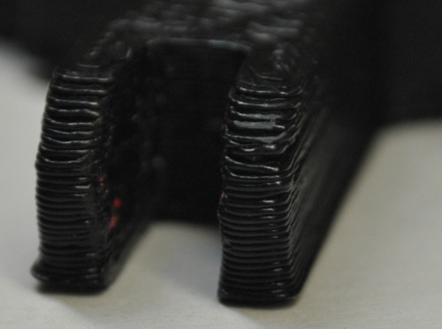
In the course of raftlessly printing dozens of mrule's Polyhedron Vertices, I've encountered a print defect I've termed "flashing" after a similar defect in injection molded parts. This is a slight flaring at the base of a part, where it meets the print bed, as well as a finite reduction in the finished part, e.g. 12mm parts are 11.5mm, 50mm parts are 49.5mm.
This is normally not a big deal, but the polyhedron vertices snap together near the base, so the flashing interferes with mating between parts. It can also cause problem if you need parts with a very specific height.
As far as I can tell, this is because our Z axis offset is set too low. For good print cohesion, we make sure smear down the first few layers of plastic as hard as possible. This causes flexing in the axis, and that layer is shorter and therefore wider. On the next layer, the same thing happens, but there is less flexing, so flare is slightly less, until the flexing is constant. This gives rise to both the height reduction and the trianglar flaring at the base of the part.
The simplest solution is to adjust the starting point up by the amount of the height reduction, however, we then lose the bed adhesion benefits of smearing the first layer, and raftless printing becomes impossible. In order to get correct, or at least workable geometry while maintaining the print bed adhesion, I've developed the following OpenSCAD script where example.stl is the stl you're altering:
file = "example.stl";
height_reduction = .8;
chamfer_radius = 0.6;
chamfer_height = 2.1;
epsilon = 0.001;
envelope_size = 1000;

//Chamfer

difference() {
    //Height Boost
    union(){
        translate([0, 0, height_reduction])
        import(file);
        linear_extrude( height =height_reduction, center = false) projection(cut = true) import(file);
    }

    minkowski() {
        difference() {
            translate([0, 0, epsilon/2])
            cube(size=[envelope_size, envelope_size, epsilon], center = true);
            linear_extrude( height = 2*epsilon, center = true) projection(cut = true) import(file);
        }
        cylinder(r1=chamfer_radius, h =chamfer_height, r2 = 0, center = false, $fn=10);
    }
}
This code simply pads the bottom of the part, so the overall height will be correct, then chamfers it using a minkowski sum, so that when flashing occurs, it brings the part out to the desired perimeter, rather than beyond it.
This hack is not ideal, it still distorts any features close to the bottom of the part. A better solution might be to modify or configure skeinforge to adjust the z-height and width over thickness on a per-layer basis, or more simply to put and extra height_reduction between the first and second layers. Despite it's shortcomings, the chamfer approach solved my mating problems with the polyhedron vertices, and it's a good first step.